Thursday 31 March 2016

Project Profile: Good craftsmanship is often modest architecture

Project: University College of the North & Thompson Regional Community Centre
Location: Thompson, Manitoba

The community centre in Thompson, Manitoba needed a facelift. The town’s University College of the North needed a new campus. Combining the two projects would create a multipurpose community meeting place. And that’s just what Doug Corbett of Architecture49 Inc. intended. “The overall vision was to create a hub in Thompson where people could congregate and enjoy recreational activities,” he says. “The new building would be a place for traditional and advanced learning.”

He added, “It would also attempt to reach out to those who have not previously felt welcome in a university college environment.” Corbett had spent ten years working in Thompson and recognized the need for a new city centre where people would naturally gather. The project was a tough sell at first. “There was a lot of negativity in the beginning. No one believed it would get built. They thought it was just another political promise. And then, once they realized it was going to happen, they were expecting to get a vanilla box,” he explains.


The new campus building has a floor area of 8,155 m2 (87,780 sq. ft.). It was designed and built in conjunction with renovations to the existing Thompson Regional Community Centre. The two buildings are connected, sharing amenities such as food services, a gymnasium, day care and a library. Also connected to the TRCC is the curling club which is clad with unpainted Z275 (G90) galvanized steel. The campus building is a four-storey structure with a visual and spiritual connection to the Burntwood River on the north side of the site.


“What we intended to do was make a ceremonial entrance to both buildings. The First Nations people have very strong connections to the river, so we wanted the buildings to have this connection as well,” says Corbett, adding that over 2,000 people came to the grand opening. “It’s a striking-looking building. The community is very proud of it. They tend to show it off quite a bit.” The flexibility and durability of steel made it a natural fit for the project. The super structure, roof, standing-seam paneling, and the studs of the buildings are steel.


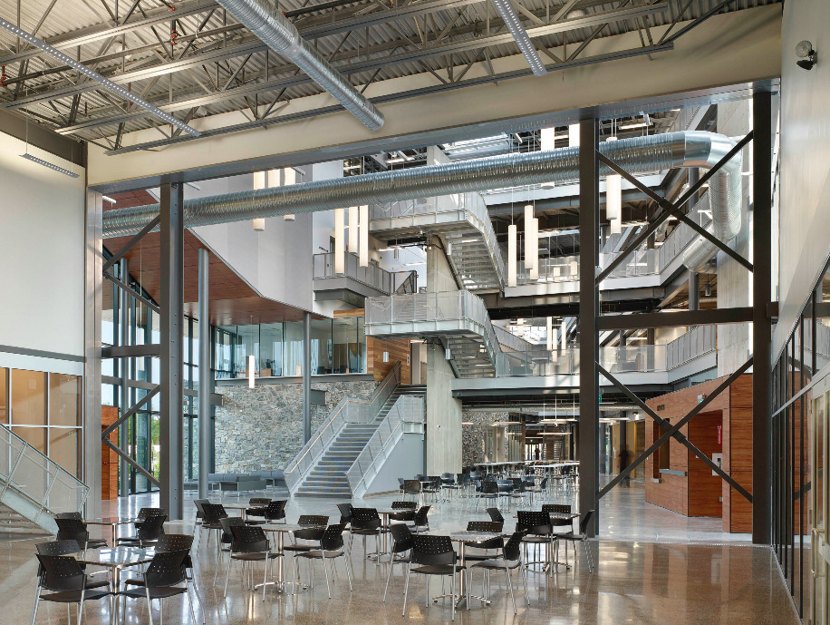
“We left a lot of the materials exposed. Steel was the main part of our design process. We wanted a natural galvanized look. The design concept was raw,” Corbett says. “One of the main advantages of using steel in a Northern climate is that you can erect it at any time of year. Steel is durable for the buildings’ purpose and climate. If a panel gets damaged, you can take it off and replace it pretty easily.”


Construction started on the Thompson Regional Community Centre in June 2010 and finished in November 2011. Work began on the University College of the North (UCN) campus in May 2011, and finished in September 2014.


“Architecture has a social responsibility. Our intent was to express the community’s values through architecture,” says Corbett. “Aboriginal youth are the fastest-growing demographic in Canada, but the lack of access to good education is a major problem facing First Nations people. The new UCN campus is an inviting destination that inspires and connects the community, and makes the First Nation students feel welcome.”

DESIGN AND CONSTRUCTION TEAM 
OWNER: Province of Manitoba
ARCHITECT: Architecture49 Inc.
CONSTRUCTION MANAGER: 
     UCN: PCL Constructors Canada
     TRCC: Akman Construction
STRUCTURAL STEEL SUPPLIER: Columns & Beams: Abesco
STRUCTURAL ENGINEERS: Crosier Kilgour & Partners
MECHANICAL & ELECTRICAL ENGINEER: WSP
CIVIL ENGINEER: Neegan Burnside Ltd.
ELECTRICAL & MECHANICAL CONTRACTOR: Wescan
WALL CLADDING SUPPLIER UCN AND TRCC: Agway Metals Inc.
MASONRY & WALL CLADDING INSTALLER UCN: Brxton Construction LP
WALL CLADDING INSTALLER TRCC & CURLING CLUB: Tri-Clad Designs Inc.

Click to download Case Study 92-15: Good craftsmanship is often modest architecture


http://www.cssbi.ca

Thursday 24 March 2016

Fire Endurance of Floor Assemblies

The National Building Code of Canada (NBCC) is the model code that specifies the structural and fire protection requirements for buildings constructed across Canada. These requirements prescribe the minimum levels of occupant safety to be achieved.

Steel construction has a long history of implementing standards and conducting tests to meet these codes. The latest series of tests have produced new fire-resistance ratings for floor assemblies using cold formed c-section joists, suitable for constructing houses and small commercial and industrial buildings. 

Steel construction has sometimes been unjustly perceived as offering reduced fire safety. Testing conducted by the National Research Council of Canada (NRC) - Institute for Research in Construction (IRC) in Ottawa, provides an indisputable third party endorsement that cold-formed steel framed floor assemblies can meet and exceed the building code requirements, and in fact out-perform the more traditional framing materials. 

Testing Program 
The fire testing conducted by NRC/IRC was part of a three year joint government and industry program. The project participants included representatives from the steel, wood and concrete industries, gypsum board and insulation manufacturers, home builders and related government agencies. Thirty-two fire tests were conducted on full scale floor assemblies framed using dimensional lumber, wood-I joists, concrete and cold-formed steel joists. Testing was done in accordance with fire endurance testing standards CAN/ULC-S101-M89 and ASTM E119. 

The time temperature curve that is specified in the CAN/ULC and ASTM standards was adhered to in all tests. The test standards also called for the floors to be loaded to 100% of strength. This was the case for all the steel framed floors and some of the wood and wood-I floors. 

Results 
In the following table, the test results show that the steel framed floors achieve a higher fire resistance than either of the wooden counterparts. For the same floor assembly construction (see Figure 1), and switching only the floor joists, the cold-formed steel joists achieved a fire resistance of 74 minutes while the dimensional wood joist achieved a rating of 69 minutes under the same loading conditions. The wood-I framed floors reached 72 minutes and the fire resistance was found to depend on the type of wood-I joist used. The effect of imposed test load was found to be significant. For the solid wood joist increasing the load from 75-100% decreased the fire resistance by 14%. The failure mode for all the floors in this comparison was structural. 


The data, published by the NRC/IRC in an internal report (IRC-IR-764), will form the basis for fire resistance ratings for floor assemblies to be listed in the NBCC. The tests outlined in the following table are baseline tests from which the various effects of insulation and resilient channel can be extrapolated. The data will eventually enable derivation of fire resistance ratings for unlisted assemblies according to the component method found in Appendix D of the NBCC. The steel industry, through the Canadian Sheet Steel Building Institute, has already developed a large series of non-loadbearing cold-formed steel framed wall assemblies that achieve the required fire-resistance and acoustic ratings and these are listed in the NBCC Part 9- Table A-9.10.3.1.A.


http://www.cssbi.ca

Tuesday 22 March 2016

Autres moyens de prouver la conformité avec le Code national de l’énergie pour les bâtiments 2011

Figure 1: Système de bâtiment en acier de vente au détail

Le Code national de l’énergie pour les bâtiments (CNEB) a été publié à l’automne de 2011. Il s’agit d’un modèle de code national qui peut être adopté par les provinces et les territoires dans la mesure où il répond à leurs besoins. À l’heure actuelle, cinq provinces ont adopté des règlements sur la conservation de l’énergie. Le CNEB s’applique à la construction de nouveaux édifices qui sont tenus de respecter les dispositions de la Section 3 du Code national du bâtiment du Canada ou du Code du bâtiment provincial applicable.

Il est possible de rendre la conception des immeubles conforme au CNEB 2011 de quatre façons : 
  1. La méthode normative (section 3.2) par laquelle les assemblages et les composants doivent satisfaire aux exigences minimales de rendement prescrites. 
  2. La méthode de remplacement simple (sous-section 3.3.3) par laquelle certains ensembles ou composants peuvent ne pas satisfaire aux exigences de rendement prescrites, tandis que d’autres ensembles ou composants dépassent les exigences de rendement prescrites, de façon telle que le rendement global de l’immeuble ne consommera pas plus d’énergie. 
  3. La méthode de remplacement détaillée (sous-section 3.3.4) par laquelle un modèle informatisé est utilisé pour établir une cible énergétique de référence pour l’enveloppe du bâtiment. Certains composants sont approuvés pour un rendement moins écoénergétiques à la condition qu’il puisse être démontré que l’enveloppe du bâtiment ne transférera pas plus d’énergie que la quantité indiquée par la cible énergétique de l’enveloppe du bâtiment. 
  4. La méthode du rendement (section 3.4) selon laquelle la méthode de remplacement est étendue pour inclure l’équipement à l’intérieur de l’immeuble (c’est-à-dire les ventilateurs, les appareils électroménagers, les ascenseurs, etc.) et un modèle informatisé sont utilisés pour s’assurer que assemblages de construction, les composants et l’équipement en agrégat ne consommeront pas plus d’énergie que la quantité indiquée par la cible énergétique de l’enveloppe du bâtiment.

La méthode normative permet une transmission thermique globale maximale pour les murs, le toit, les portes et les fenêtres du bâtiment. L’avantage de la méthode normative c’est qu’elle est très facile à appliquer; toutefois, elle impose parfois l’obligation de satisfaire aux objectifs du code de l’énergie relativement à l’enveloppe du bâtiment. Cela peut résulter en une conception trop poussée de l’isolant des murs et du toit. Avec un peu plus d’efforts, une solution plus rentable pourrait être obtenue en appliquant les autres options du CNEB : la méthode de remplacement simple ou la méthode du rendement. 


Exemple de la méthode de remplacement simple 
La méthode de remplacement simple démontre que la somme des aires des ensembles verticaux (ou horizontaux) de l’enveloppe du bâtiment multipliée par leur transmission thermique globale ne dépasse pas celle des assemblages de construction correspondants du bâtiment de référence. Le bâtiment de référence utilisé pour la méthode de remplacement simple est le même que l’on utilise pour la méthode normative. Si certains composants sont plus éco-énergétiques que ceux préconisés dans la méthode normative, il est permis de prendre en compte ce gain de rendement dans le calcul du remplacement. 

Le choix de la méthode de remplacement simple peut présenter un avantage économique considérable pour les murs en tôles d’acier isolées et les structures de toit. Les données indiquées dans le Tableau 1 résument les calculs effectués pour trois villes au Canada avec deux configurations différentes de construction qui seraient semblables à l’immeuble à commerces de détail illustré à la figure 1. Ces calculs sont pour la surface des murs, mais un processus similaire peut être utilisé pour le toit. 


Les étapes pour utiliser la méthode de remplacement simple sont les suivantes :
  • La ligne 1 énumère les degrés-jours de chauffage (DJC) qui proviennent des données climatiques pour l’emplacement spécifique. Les données climatiques indiquées à l’Annexe C du Code national du bâtiment du Canada peuvent être utilisées à moins que l’autorité locale ne requière d’autres valeurs. Le CNBC 2010 a été utilisé dans cet exemple. 
  • Les facteurs U maximums de la ligne 2 pour les murs proviennent du Tableau 3.2.3.1 du CNEB et dépendent des DJC. 
  • Les facteurs U maximums de la ligne 3 pour la fenestration proviennent du Tableau 3.2.2.3 du CNEB. Remarque : les facteurs U maximums pour les portes sont les mêmes que pour la fenestration. Ces valeurs dépendent également du DJC.
  • Le rapport de l’aire maximale totale acceptable de la fenestration et des portes verticales avec l’aire de mur brute (RFPM) est déterminé conformément à l’article 3.2.1.4. Pour des DJC inférieurs à 4000, le RFPM maximal = 40 %. Pour des DJC entre 4000 et 7000, le RFPM maximal = (2 000 - 0,2 x DJC)/3000. Pour des DJC de plus de 7000, le RFPM minimal = 20 %.
  • En effectuant le calcul de remplacement simple de l’article 3.3.3.2, le facteur U maximal pour le bâtiment de référence du CNEB se calcule comme suit et illustré à la ligne 5 : Max U (bât. réf.) = (1 - Max_RFPM)(Max Umur) + (MAX_RFPM)(max UFen) 
  • Le RFPM à la ligne 6 est le rapport pour le bâtiment proposé. Dans cet exemple deux rapports sont sélectionnés : 8 % et 20 % 
  • La valeur Max U (mur) à la ligne 7 est calculée comme suit : Max U (mur) = [(Max U (bât. réf.) - (RFPM)(Max Ufen)]/ (1 - RFPM) 
  • Les valeurs R indiquées aux lignes 8 et 9 sont des conversions du facteur U de la ligne 7. 
  • Les valeurs R indiquées à la ligne 10 sont tirées du Tableau 3.2.2.2 pour le CNEB et elles représentent les exigences normatives pour les murs opaques du bâtiment. 
Les avantages de la méthode de remplacement simple sont démontrés dans la comparaison des lignes 9 et 10 du Tableau 1. Il convient de noter que les valeurs R minimales admissibles indiquées à la ligne 9 sont bien en deçà des valeurs R communément appliquées dans les ensembles muraux en tôles d’acier isolées.

La méthode du rendement 
La méthode du rendement fait appel à la modélisation énergétique pour comparer la consommation d’énergie annuelle d’une conception proposée par rapport à celle d’un bâtiment « de référence », qui possède la même taille et la même forme que celles de la conception proposée, mais qui est peu compatible avec le code de l’énergie dans tous les autres aspects. La méthode du rendement permet de rendre un projet conforme au code de l’énergie par le remplacement de certains systèmes moins performants, comme l’enveloppe de l’immeuble, par des systèmes plus performants comme de l’équipement mécanique ou un éclairage plus efficace. L’objectif de la méthode du rendement est de permettre l’adaptabilité à une plus grande flexibilité en matière de conception. 

La société Morrison-Hershfield a été mandatée par l’ICTAB pour entreprendre la modélisation d’un système de bâtiment en acier à commerces de détail semblable à celui illustré à la figure 1. Le modèle énergétique a été développé à l’aide du programme EnergyPlus v8.4 et il a pris en compte les variables suivantes : 
  • Trois zones climatiques (4, 6 et 7A) 
  • Deux systèmes de CVCA 
  • Économies d’éclairage : De 0 à 45 % de la base de référence du CNEB. 
  • Valeurs de vitrage : U-0,5 à U-0,25 
  • Valeurs R des murs et du toit : R-10 à R-40 
  • RFPM de 8 % et 20 % 
  • Facteur F de la dalle : R-10 à R-7,5 
Compte tenu du nombre de variables, un total de 20 736 différentes options ont été analysées représentant différentes combinaisons. Les résultats ont été présentés de façon graphiquement similaire au résultat illustré à la figure 2. Ces courbes illustrent diverses options qui seraient conformes aux exigences du code énergétique. Par exemple, le fait de comparer la ligne rouge avec la ligne jaune indique la manière dont le code peut être respecté avec des murs à R15 et R20 respectivement. Des courbes similaires peuvent être générées en fonction d’autres variables. Le rapport de Morrison-Hershfield est disponible sur le site Web de l’ICTAB à http://cssbi.ca/fr/produits/systemes-de-batimenten-acier. La principale conclusion de cette étude a été de faire la démonstration qu’il existe une grande variété d’options pour répondre aux exigences du code de l’énergie, et que la solution la plus rentable n’est pas simplement d’ajouter plus d’isolant dans les murs et dans la structure de toit. 


Ressources additionnelles 
Il existe un certain nombre de ressources disponibles pour prouver la conformité avec les codes de l’énergie y compris les suivantes : 
http://www.cssbi.ca

Thursday 17 March 2016

Alternative Means of Proving Compliance with the National Energy Code for Buildings 2011

Figure 1: Retail Steel Building System

The National Energy Code for Buildings (NECB) was published in the fall of 2011. It is a National Model Code that can be adopted by the Provinces and Territories to the extent it meets their needs. At the present time five provinces have adopted some energy conservation regulations. The NECB applies to the construction of new buildings that are required to meet the provisions of Part 3 of the National Building Code of Canada, or the applicable Provincial Building Code.

There are four paths through which building designs may comply with NECB 2011: 
  1. The Prescriptive Path (Section 3.2) in which assemblies and components must meet minimum prescribed performance requirements.
  2. The Simple Trade-off Path (Sub-Section 3.3.3) in which certain assemblies or components may not meet the prescribed performance requirements, while other assemblies or components exceed the prescribed performance requirements, such that the overall performance of the building will not use more energy. 
  3. The Detailed Trade-off Path (Sub-Section 3.3.4) in which a computer model is used to establish a reference building envelope energy target. Some components are permitted to be less energy efficient provided it can be demonstrated the building envelope will not transfer more energy than the building envelope energy target. 
  4. The Performance Path (Section 3.4) in which the Trade-Off methodology is extended to include equipment inside the building, (i.e. fans, appliances, elevators, etc.) and a computer model is used to determine that the building assemblies, components and equipment in aggregate, will not use more energy than the reference building envelope energy target.

The Prescriptive Path provides maximum overall thermal transmittance for the building walls, roof, fenestration and doors. The advantage of the Prescriptive Path is that it is very easy to use; however, it often places the full burden for meeting the energy code targets on the building envelope. This can result in the insulated wall and roof assemblies being over-designed. With a little additional work a more cost-efficient solution can be obtained by using the other NECB options; the Simple Trade-off Path or the Performance Path. 


Example of the Simple Trade-Off Path 
The Simple Trade-off Path demonstrates that the sum of the areas of vertical (or horizontal) assemblies of the building envelope multiplied by their respective overall thermal transmittance is not more than the corresponding assemblies in the reference building. The reference building for the Simple Tradeoff Path is the same building used with the Prescriptive Path. If certain components are more energy efficient than those prescribed in the Prescriptive Path, the trade-off calculation is permitted to take this increased performance into account. Taking advantage of the Simple Trade-off Path can provide a significant cost advantage for insulated sheet steel wall and roof assemblies. The data given in Table 1 summarizes the calculations for three cities in Canada with two different building configurations that would be similar to the retail building shown in Figure 1. These calculations are for the wall area, but a similar process can be used for the roof.

The steps for using the simple trade-off method are as follows:
  • Line 1 lists the Heating Degree Days (HDD) that comes from the climatic data for the specific location. The climatic data in Appendix C of the National Building Code of Canada can be used unless the local jurisdiction requires other values. NBCC 2010 has been used in this example. 
  • The maximum U-factors in Line 2 for the walls come from Table 3.2.3.1 in NECB and depend on the HDD. 
  • The maximum U-factors in Line 3 for the fenestration come from Table 3.2.2.3 in NECB. Note that the maximum U-factors for doors are the same as for the fenestration. These values also depend on the HDD. 
  • The maximum allowable total vertical fenestration and door area to gross wall area ratio (FDWR) is determined in accordance with Article 3.2.1.4. For HDD less than 4000, the maximum FDWR = 40%. For HDD between 4000 and 7000, FDWR = (2000-0.2xHDD)/3000. For HDD over 7000, the minimum FDWR = 20%. 
  • Using the simple trade-off calculation from Article 3.3.3.2, the maximum U-factor for the NECB reference building is calculated as follows and given in Line 5: Max U (ref. bldg.) = (1-Max_FDWR)(Max Uwall) + (Max_FDWR)(Max UFen) 
  • The FDWR in Line 6 is the ratio for the proposed building. In this example two ratios are selected: 8% and 20%. 
  • The Max U (Wall) given in Line 7 is calculated as follows: Max U (Wall) = [(Max U (ref. bldg.)- (FDWR)(Max Ufen)]/ (1-FDWR) 
  • The R-values given in Lines 8 and 9 are conversions for the U-factor from Line 7. 
  • The R-values given in Line 10 are taken from Table 3.2.2.2 for the NECB and are the prescriptive requirements for opaque building walls. 
The benefits of the Simple Trade-off Path are demonstrated in the comparison of Lines 9 and 10 in Table 1. It is worth noting that the minimum allowable R-values shown in Line 9 are well below the R-values commonly used in insulated sheet steel wall assemblies.

The Performance Path
The Performance Path uses the energy modeling to compare the annual energy use of a proposed design against that of a “baseline” building, which has the same size and shape as the proposed design, but is minimally compliant with the energy code in all other aspects. The Performance Path allows for a project to be complaint with the energy code by trading off lower performing systems, such as the building envelop, with higher performing systems, such as higher efficiency mechanical equipment or lighting. The goal of the Performance Path is to allow compliance with greater design flexibility. 

The CSSBI commissioned Morrison-Hershfield to undertake Performance Path modeling of a retail steel building system similar to the one shown in Figure 1. The energy model was developed using EnergyPlus v8.4 and considered the following variables: 
  • Three climate zones (4, 6 and 7A) 
  • Two HVAC systems 
  • Lighting savings: 0% to 45% of NECB baseline 
  • Glazing values: U-0.5 to U-0.25 
  • Wall and roof R-values: R-10 to R-40 
  • FDWR of 8% and 20% 
  • Slab F-Factor: R-10 to R-7.5 
Given the number of variables, a total of 20,736 different options were analyzed representing different combinations. The results were presented graphically similar to the output shown in Figure 2. These curves illustrate various options that would comply with the energy code. For example, comparing the red line to the yellow line shows how the code can be met with an R15 and R20 wall respectively. Similar curves can be generated based on other variables. The report from Morrison-Hershfield is available on the CSSBI web site at www.cssbi.ca/products/steel-building-systems. The principal conclusion from this study was the demonstration that there are a wide variety of options for meeting the energy code requirements, and the most cost-effective solution is not to simply add more insulation in the wall and roof assemblies.


Additional Resources 
There are a number of resources available to prove compliance with the energy codes including the following: 

http://www.cssbi.ca

Thursday 10 March 2016

Canadian Sheet Steel Building Institute Releases Industry-Wide Environmental Product Declaration (EPD) for Roll Formed Steel Panels

CAMBRIDGE, ON - The Canadian Sheet Steel Building Institute (CSSBI) released the first industry-wide Environmental Product Declaration (EPD) for Roll Formed Steel Panels manufactured in Canada. The EPD quantifies the “cradle-to-gate” with options. Therefore, the life cycle stages taken into account include raw materials supply, transportation, the North American manufacturing of hot dip galvanized coils, paint coil coating, panel roll forming and end of life recycling. Based on a peer-reviewed life cycle assessment (LCA), this EPD is a transparent tool that can help achieve credits required for building certification within LEED® v4 and other green building rating programs.

This is the first industry-wide assessment of the life cycle environmental impacts of roll formed steel panels. The panels are roll formed from Galvanized (100% zinc) or Galvalume (55% aluminum, 45% zinc) coated steel that may be painted using a continuous coil coating process. A variety of profiles are available for steel roofing, decking and cladding applications. Roll formed panels may be used in residential, agricultural, industrial, commercial and institutional building construction.

The EPD is available for download at http://www.cssbi.ca/resources

As an association, the CSSBI and its members recognize that sustainable construction is an important and essential part of our world’s long-term ecological and economical prosperity. This EPD and other research on the topic of sustainability demonstrates that roll formed steel panels for building applications can play a significant role in any sustainable project.

The CSSBI is Canada’s foremost authority on sheet steel, its products, and its many applications. The CSSBI is an industry association responsible for the development and dissemination of industry standards. A source for technical information and resources, the CSSBI provides expert guidance to the general public and sheet steel manufacturers alike. For more information, visit http://www.cssbi.ca or follow us on Twitter @CSSBI.


http://www.cssbi.ca

Thursday 3 March 2016

Prepainted Steel Cladding and Light Steel Framing Combat Harsh Conditions

Project Profile: Jonah Amitnaag School and Community Centre
Baker Lake, Nunavut

The geographic centre of Canada, Baker Lake, is the only inland Inuit community in Canada, with access by water to Hudson Bay through Chester eld Inlet. The concept for the new 4,580m2 (49,300 sq. ft) school, occupied since August 2004, ‘Broad Horizons’, relates to the school’s location adjacent to Baker Lake, as well as the ideals of the educational process.
The gentle arching plan of the school takes advantage of the school’s location central to the community overlooking Baker Lake. A central triangular shaped atrium punctuated by a central stair and bridge, expands outward toward the lake in both plan and section.The school is designed to function both as a school and as a community library. After hours both the library and gymnasium can be accessed directly from the entrance vestibule without entering the rest of the building. The foundation is built on141mm (5-1/2”) diameter rock socketed piles elevating the school over a sloped site and allowing the community area snow melt to drain below. Access is provided by a series of galvanized steel stairs and ramps.
Good Building Practice Guidelines
The Nunavut Government has prepared guidelines for good building practice for northern facilities to assist designers with reducing problems and eliminating past mistakes. Building overhangs are discouraged and special attention is encouraged regarding mechanical air intakes and exhausts regarding ice build-up and infiltration of fine blowing snow. The new school reflects these guidelines.
Massing is straight forward without overhangs. The envelope design is simple, sheathing to the walls, soffit and roof is covered in a continuous air-vapour barrier with semi-rigid non-combustible insulation and prefinished steel on girts and clips on top. Outside field painting to wood or metal does not last in this dry harsh climate. To reduce maintenance and achieve a long-lasting finish, Architects Smith Carter of Winnipeg selected prefinished steel for exterior walls, soffit and roof and galvanized steel for exterior ramps, handrails and canopy extensions.
Elevations are enlivened by a variety of prefinished steel profiles, colours and finishes. The majority of the facade is clad in 7/8” corrugated Z275 galvanized steel panels in 0.66mm and 0.81mm (0.026” and 0.032”) HMP Series Regent Grey QC6082, 0.81mm (0.032”) 10000 Series, Twilight Blue QC3644 and 0.81mm (0.032”) Metallic Series Bright Silver QC2624. Flat prefinished steel panels are also used to provide a contrasting texture at window areas. Primrose Yellow QC3729 is used between windows, with Silver.


http://www.cssbi.ca